|
|
|
INSTALLING HEATED GRIPS ON PRE-'96 ST1100
This is a describtion of how I installed a pair of Hein Gericke heated grips on my '92
ST1100 (no accessory lead wire like on the '96 and newer models) in combination with a
Vista Cruise throttle lock.
These grips are the more expensive model available from H.G., around €52 Euro's. See http://www.hein-gericke.com for shop info. These
grips come with a switch which has 3 selections;
The 48W selection can be called hot. It takes a couple of miles to really heat up, but once up to work temperatures it can hardly be touched barehanded. When riding with thick gloves around zero centigrade my hands get very warm with the exception of the pinky finger. I usually have to switch to the ON selection because the START selection simply becomes too warm. The grips are very stury, all wires are insulated in the rubber and the wire connections into the grips are very strong yet flexible as you can see on the pictures below.
The heated grip set consists of the grips, the wires coming together from the grips in some connections and from the connections out into the switch, a plus and a minus wire. The set further includes 2 tie rips, 2 wire fusers and a bracket to mount the switch on a conventional steering bar. Since there is no accesory connection on my '92 model I had to make a seperate circuit for the grips with a relay to ensure the grips would only be on when the ignition was switched on to prevent an accidental or eleborate battery drain (which would also disengage the alarm). The other option would have been to directly tap the plus wire into the ignition or light circuit, but this is not a safe option. The ignition / light circuit are not designed to carry an extra 48W current and could melt / burn / blow up the circuit, leaving you not only without warm hands but obviously also without lights or worse..ignition. So I installed the ground wire from the grips to the frame and the plus wire from the plus of the battery via a 10 Amps fuse and a relay to the grips and switch. The relay is a 12V relay with 4 connections. One connection is via the 10 Amps fuse from the battery, another is for the plus wire from the grips, a third is wired to ground and I installed the fourth connection to the ignition wire that comes from the fusebox. When the ignition is turned on, current will flow thru the ignition cicrcuit. A very small current of this (around 3 Amps) will go to the relay. This in turn will switch the relay on so that a high current (max around 48W) from the battery can flow thru the relay to the grips (providing of course the gripswitch is switched to ON / START).
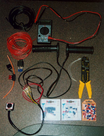
In order to install this setup some extra stuff was required. On the picture below you can see most of the stuff I used. You see a voltmeter, some black and red coloured electrical wire (2.5mm), the four-pole 12V relay with wireconnectors allready attached, a weatherproof 10 Amps fuse, two transparent tie rips (I bought some more), a wire stripper and connector 'squeezer', O-ring connectors for the ground and plus connections, wire-to-wire connectors (somewhat sealed) and the grips with switch.
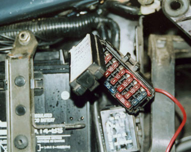
The most difficult thing was to find a proper place to connect the switchwire from the relay. The fusebox proved to have a good and weatherproof connection point. I did not want to use the wirefusers that came with the gripset because it actually cuts the original wire in two. I was not convinced of the durability of this connection so I searched the fusebox (the upper one) for a better one. The fusebox can be taken of it's mounting point easily. If you turn the underside towards you it will unhook the lower part. Then just lift upwards to unhook the upper part. As you can see on the lower picture, there are two holes in the lower part of the fusebox which can be used to route wires from behind into the fusebox and then upwards alongside the fuses. This way the fusebox lid can still be closed. The middle fuse is for the ignition wire. Power comes from the left to the right, so I connected the wire to the right side so that the switchwire would also be protected by the ignition fuse.
I installed wire-to-wire connectors between most of the wires to quickly disconnect or
replace sections in case of a roadside problem or repair.
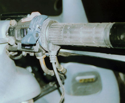
After installing the wires I had one more problem, because I wanted to install the grips
in combination with a Vista Cruise throttle lock. With a sharp pair of scissors I cut of
the thick edge on the outside of the grip to prevent bonding with the bar end weight and a
piece of the thick ring on the inside (left) to prevent bonding with the VC throttle lock.
There was no cutting necessary for the left grip, it went on without problems. It's very
important to leave enough play in the wire going to the throttle grip because it needs
room to turn. I routed the wires along the OEM wiring harness and used tie rips on several
points to fix it into position. Be sure to check the play of the throttle wire when
throttling and steering full left and right before fixing this wire with tie rips.
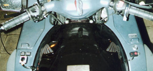
Below you can see the wires coming from the grips into defualt openings under the air filter cover. On the left you can see the switch mounted (you can stick it right on) below the ABS/TCS switches. The switch on the right is from the Red Alert alarm. With a solder gun I melted a hole in the side of the left fairing to route the wires to the connectors lying below the fairing.
This operation took me about 4 hours spread over two days. I took my time and was new in this kind of work, normally I let someone else do this kind of stuff. A lot of time was also spent asking for information on the PanEuro mailing list and friends on what the best way was to safely hook up the wires. My thanks go out to Martin and Michel from the list and to Victor for their advice and help in this matter. To quote Martin's famous words : "..one small step for electrical engineering, one giant step for Emile..".